verilog笔记:运动码表的硬件描述语言实现

继上一篇logisim笔记:基本使用及运动码表的实现,我还使用了硬件描述语言对同样需求的运动码表进行了实现,那么就在这里一并也总结一下吧。

References

电子文献:
https://blog.csdn.net/leon_zeng0/article/details/78441871
https://www.cnblogs.com/douzi2/p/5147151.html
https://blog.csdn.net/FPGADesigner/article/details/82425612


整体设计

由于需求与使用Logisim实现时一致,因此我的设计思路也基本沿用上一篇博文中提到的方案。但是要注意的是,这里的000状态并不在作为按键抬起之后的中间态,而是进入系统时的一个默认初始状态。


Vivado中一些高亮的含义

在具体的代码之前,我还想先归纳一下本次实践过程中遇到的和发现的Vivado中一些高亮提醒的含义。

  1. 土黄色高亮

    土黄色高亮出现的原因主要可能是下面三种情况:
    1. 定义重复。
    2. 定义放在了调用处的后面(identifier used before its declaration)。
    3. 声明残缺(empty statement)。
  2. 蓝色高亮

    1. 含有undeclared symbol。
    2. 和上面土黄色高亮相搭配出现,有定义重复时指明重复定义的位置。

16位数值比较器

该模块用于比较两个16位二进制数的大小,以确定是否需要存入记录的数据。代码如下:

1
2
3
4
5
6
7
8
9
10
11
12
13
14
module _16bit_Comp(
input [15:0] A,
input [15:0] B,
output reg Y
);

always @ (A or B)
begin
if(A < B)
Y <= 1;
else
Y <= 0;
end
endmodule


16位寄存器

TMRecord表示码表暂停时的读数,regRecord表示寄存器中已经存储的记录,初始值为9999。控制信号有使能信号和reset信号。当收到reset信号时,直接将记录改为9999。当有使能信号时,将TMRecord记录下来。代码如下:

1
2
3
4
5
6
7
8
9
10
11
12
13
14
15
16
17
18
19
20
module _16bit_Reg(
input enable,
input [15:0] TMRecord,
input [15:0] regRecord,
input [15:0] maxDefault,
input reset,
input clock,
output reg [15:0] next_record
);

always @ (reset or enable)
begin
if(reset & enable)
next_record <= maxDefault;
else if(enable)
next_record <= TMRecord;
else
next_record <= regRecord;
end
endmodule


数码管显示驱动

将BCD码转化为7位二进制数,即对应7段数码管,用于显示。

1
2
3
4
5
6
7
8
9
10
11
12
13
14
15
16
17
18
19
20
21
22
module watchDrive(
input [3:0] BCD,
output reg [6:0] light
);

always @ (BCD)
begin
case(BCD)
0: light = 7'B0111111;
1: light = 7'B0001001;
2: light = 7'B1011110;
3: light = 7'B1011011;
4: light = 7'B1101001;
5: light = 7'B1110011;
6: light = 7'B1110111;
7: light = 7'B0011001;
8: light = 7'B1111111;
9: light = 7'B1111011;
default: light = 7'B0111111;
endcase
end
endmodule


顶层文件

该部分主要包括对各个变量的定义和初始化;状态转换,即共设计了5种状态,对应不同的功能,当按下不同按键时,选择对应的状态并作为次态;数码管的显示与进位,即对数码管4个位置依次改动,从低位开始计算,当进位时产生进位信号到下一位。当有重置信号(这里使用的是reset和start的上升沿)时清零。

1
2
3
4
5
6
7
8
9
10
11
12
13
14
15
16
17
18
19
20
21
22
23
24
25
26
27
28
29
30
31
32
33
34
35
36
37
38
39
40
41
42
43
44
45
46
47
48
49
50
51
52
53
54
55
56
57
58
59
60
61
62
63
64
65
66
67
68
69
70
71
72
73
74
75
76
77
78
79
80
81
82
83
84
85
86
87
88
89
90
91
92
93
94
95
96
97
98
99
100
101
102
103
104
105
106
107
108
109
110
111
112
113
114
115
116
117
118
119
120
121
122
123
124
125
126
127
128
129
130
131
132
133
134
135
136
137
138
139
140
141
142
143
144
145
146
147
148
149
150
151
152
153
154
155
156
157
158
159
160
161
162
163
164
165
166
167
168
169
170
171
172
173
174
175
176
177
178
179
180
181
182
183
184
185
186
187
188
189
190
191
192
193
194
195
196
197
198
199
200
201
202
203
204
205
206
207
208
209
210
211
212
`timescale 1ns / 1ps
//top module
module runningwatch(
input start,
input stop,
input store,
input reset,
input CLK,
output reg TM_EN, //enable the timer
output reg SD_EN, //enable register
output reg DP_SEL, //the screen show which data
output reg [15:0] regRecord, //data the register storing
output reg [15:0] TMRecord, //timer data
output [6:0] tenmsLight, hunmsLight, onesLight, tensLight
);

reg [3:0] tenMS, hunMS, oneS, tenS; //four 4bit digits from small to high and each from 0 to 9
reg tenmsup, hunmsup, onesup; //the signals if the bigger digit than itself should add

//allocate state
parameter S0 = 3'B000;
//initial state
parameter S1 = 3'B001;
//TIMING:timer set as 00.00,record does not change,show timer,timer counts,TM_EN = 1, SD_EN = 0, DP_SEL = 0
parameter S2 = 3'B010;
//PAUSE:timer does not change,record does not change,show timer,timer does not count,TM_EN = 0, SD_EN = 0, DP_SEL = 0
parameter S3 = 3'B011;
//UPDATE:timer does not change,record set as timer,show register,timer does not count,TM_EN = 0, SD_EN = 1, DP_SEL = 1
parameter S4 = 3'B100;
//KEEP:timer does not change,record does not change,show register,timer does not count,TM_EN = 0, SD_EN = 0, DP_SEL = 1
parameter S5 = 3'B101;
//RESET:timer set as 00.00,record set as 99.99,show timer,timer does not count,TM_EN = 0, SD_EN = 1, DP_SEL = 0

reg [2:0] state;
reg [2:0] next_state;

//reg CLK;
initial //only run once
begin
regRecord = 16'B0010011100001111;
TMRecord = 16'B0000000000000000;

state = S0;

tenMS = 0; hunMS = 0; oneS = 0; tenS = 0;
end

//to judge if store the timer's data
wire new;
reg newRecord;
_16bit_Comp comparator(TMRecord, regRecord, new); //compare
always @ (new)
newRecord = new;

reg [15:0] MAX = 16'B0010011100001111;

//sequential logic part
always @ (posedge CLK) //update the state at each posedge
begin
state <= next_state;
end

//combinatory logic part
//state transform
always @ (state or start or stop or store or reset or newRecord)
begin
next_state = S0; //if not press the key, back to the initial state

case(state)

S0: //initial state
begin
TM_EN = 0; SD_EN = 0; DP_SEL = 0;
if(start) begin next_state = S1; TM_EN = 1; SD_EN = 0; DP_SEL = 0; end
else if(stop) begin next_state = S2; TM_EN = 0; SD_EN = 0; DP_SEL = 0; end
else if(store & newRecord) begin next_state = S3; TM_EN = 0; SD_EN = 1; DP_SEL = 1; end
else if(store & ~newRecord) begin next_state = S4; TM_EN = 0; SD_EN = 0; DP_SEL = 1; end
else if(reset) begin next_state = S5; TM_EN = 0; SD_EN = 1; DP_SEL = 0; end
else begin next_state = S0; TM_EN = 0; SD_EN = 0; DP_SEL = 0; end
end

S1: //TIMING
begin
TM_EN = 1; SD_EN = 0; DP_SEL = 0;
if(start) begin next_state = S1; TM_EN = 1; SD_EN = 0; DP_SEL = 0; end
else if(stop) begin next_state = S2; TM_EN = 0; SD_EN = 0; DP_SEL = 0; end
else if(store & newRecord) begin next_state = S3; TM_EN = 0; SD_EN = 1; DP_SEL = 1; end
else if(store & ~newRecord) begin next_state = S4; TM_EN = 0; SD_EN = 0; DP_SEL = 1; end
else if(reset) begin next_state = S5; TM_EN = 0; SD_EN = 1; DP_SEL = 0; end
else begin next_state = S0; TM_EN = 0; SD_EN = 0; DP_SEL = 0; end
end

S2: //PAUSE
begin
TM_EN = 0; SD_EN = 0; DP_SEL = 0;
if(start) begin next_state = S1; TM_EN = 1; SD_EN = 0; DP_SEL = 0; end
else if(stop) begin next_state = S2; TM_EN = 0; SD_EN = 0; DP_SEL = 0; end
else if(store & newRecord) begin next_state = S3; TM_EN = 0; SD_EN = 1; DP_SEL = 1; end
else if(store & ~newRecord) begin next_state = S4; TM_EN = 0; SD_EN = 0; DP_SEL = 1; end
else if(reset) begin next_state = S5; TM_EN = 0; SD_EN = 1; DP_SEL = 0; end
else begin next_state = S0; TM_EN = 0; SD_EN = 0; DP_SEL = 0; end
end

S3: //UPDATE
begin
TM_EN = 0; SD_EN = 1; DP_SEL = 1;
if(start) begin next_state = S1; TM_EN = 1; SD_EN = 0; DP_SEL = 0; end
else if(stop) begin next_state = S2; TM_EN = 0; SD_EN = 0; DP_SEL = 0; end
else if(store & newRecord) begin next_state = S3; TM_EN = 0; SD_EN = 1; DP_SEL = 1; end
else if(store & ~newRecord) begin next_state = S4; TM_EN = 0; SD_EN = 0; DP_SEL = 1; end
else if(reset) begin next_state = S5; TM_EN = 0; SD_EN = 1; DP_SEL = 0; end
else begin next_state = S0; TM_EN = 0; SD_EN = 0; DP_SEL = 0; end
end

S4: //KEEP
begin
TM_EN = 0; SD_EN = 0; DP_SEL = 1;
if(start) begin next_state = S1; TM_EN = 1; SD_EN = 0; DP_SEL = 0; end
else if(stop) begin next_state = S2; TM_EN = 0; SD_EN = 0; DP_SEL = 0; end
else if(store & newRecord) begin next_state = S3; TM_EN = 0; SD_EN = 1; DP_SEL = 1; end
else if(store & ~newRecord) begin next_state = S4; TM_EN = 0; SD_EN = 0; DP_SEL = 1; end
else if(reset) begin next_state = S5; TM_EN = 0; SD_EN = 1; DP_SEL = 0; end
else begin next_state = S0; TM_EN = 0; SD_EN = 0; DP_SEL = 0; end
end

S5: //RESET
begin
TM_EN = 0; SD_EN = 1; DP_SEL = 0;
if(start) begin next_state = S1; TM_EN = 1; SD_EN = 0; DP_SEL = 0; end
else if(stop) begin next_state = S2; TM_EN = 0; SD_EN = 0; DP_SEL = 0; end
else if(store & newRecord) begin next_state = S3; TM_EN = 0; SD_EN = 1; DP_SEL = 1; end
else if(store & ~newRecord) begin next_state = S4; TM_EN = 0; SD_EN = 0; DP_SEL = 1; end
else if(reset) begin next_state = S5; TM_EN = 0; SD_EN = 1; DP_SEL = 0; end
else begin next_state = S0; TM_EN = 0; SD_EN = 0; DP_SEL = 0; end
end

default: begin next_state = S0; TM_EN = 0; SD_EN = 0; DP_SEL = 0; end //default initial state
endcase
end

//reset to zero
always @ (posedge reset or posedge start)
begin
tenMS <= 0; hunMS <= 0; oneS <= 0; tenS <= 0;
TMRecord <= 0;
end

//the followings are which have stated before:
//reg [3:0] tenMS, hunMS, oneS, tenS are four 4bit digits from small to high and each from 0 to 9
//reg tenmsup, hunmsup, onesup are the signals if the bigger digit than itself should add
//timer, divide into four digits
//10ms
always @ (posedge CLK)
begin
if(TM_EN)
begin
TMRecord = TMRecord + 1;
if(tenMS < 9)
begin tenMS <= tenMS + 1; tenmsup <= 0; end
else
begin tenMS <= 0; tenmsup <= 1; end
end
end
//100ms
always @ (posedge tenmsup)
begin
if(TM_EN)
begin
if(hunMS < 9)
begin hunMS <= hunMS + 1; hunmsup <= 0; end
else
begin hunMS <= 0; hunmsup <= 1; end
end
end

//1s
always @ (posedge hunmsup)
begin
if(TM_EN)
begin
if(oneS < 9)
begin oneS <= oneS + 1; onesup <= 0; end
else
begin oneS <= 0; onesup <= 1; end
end
end

//10s
always @ (posedge onesup)
begin
if(TM_EN)
begin
if(tenS < 9)
tenS <= oneS + 1;
else
oneS <= 0;
end
end

//save to the register
wire [15:0] newReg;
_16bit_Reg register(SD_EN, TMRecord, regRecord, MAX, reset, CLK, newReg);
always @ (newReg)
regRecord = newReg;

//change BCD to tube lights
watchDrive TENms(tenMS, tenmsLight);
watchDrive HUNms(hunMS, hunmsLight);
watchDrive ONEs(oneS, onesLight);
watchDrive TENs(tenS, tensLight);

endmodule


仿真文件

最后我们还需要自行编写一个仿真文件。

1
2
3
4
5
6
7
8
9
10
11
12
13
14
15
16
17
18
19
20
21
22
23
24
25
26
27
28
29
30
31
32
33
34
35
36
37
38
39
40
41
42
43
44
45
46
47
48
49
50
51
52
53
54
module simulateFile();
reg start, stop, store, reset;
wire TM_EN, SD_EN, DP_SEL;
wire [15:0] regRecord;
wire [15:0] TMRecord;
wire [6:0] tenmsLight;
wire [6:0] hunmsLight;
wire [6:0] onesLight;
wire [6:0] tensLight;
reg CLK;

runningwatch watch(start, stop, store, reset, CLK,
TM_EN, SD_EN, DP_SEL, regRecord, TMRecord,
tenmsLight, hunmsLight, onesLight, tensLight);
initial
begin
CLK = 0;
start = 0;
stop = 0;
store = 0;
reset = 0;
end

begin
always
//generate clock signal
forever #10 CLK = ~CLK;

//always #100
//{start, stop, store, reset} = 4'B0000;
//begin start = 0; stop = 0; store = 0; reset = 0; end
always
begin
#50
{start, stop, store, reset} = 4'B0001;
#50
{start, stop, store, reset} = 4'B1000;
#500
{start, stop, store, reset} = 4'B0100;
#50
{start, stop, store, reset} = 4'B0010;
#50
{start, stop, store, reset} = 4'B1000;
#50
{start, stop, store, reset} = 4'B0100;
#100
{start, stop, store, reset} = 4'B0010;
#50
{start, stop, store, reset} = 4'B0001;
#50
$stop; //stop simulation
end
end
endmodule


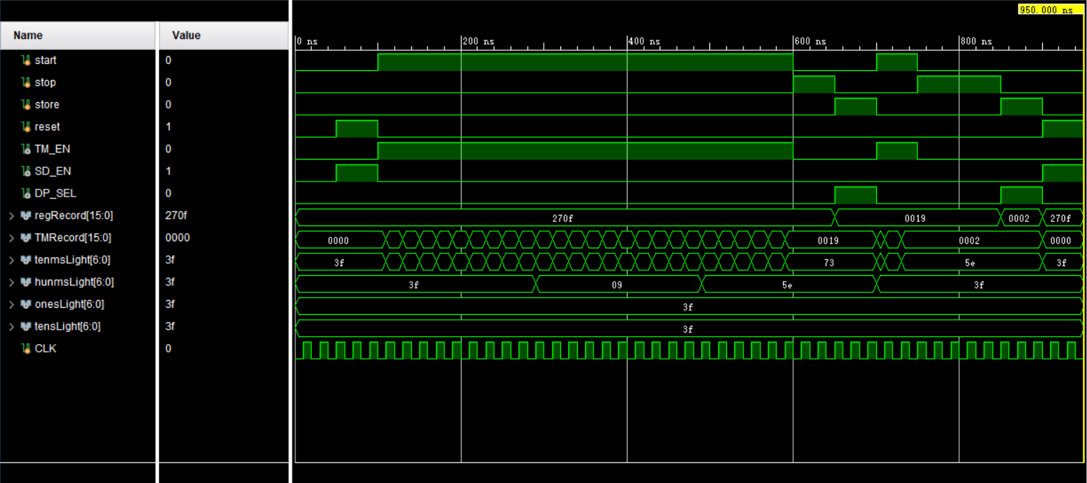
仿真结果

Run simulation,得到如下输出波形图。


遇到的问题

  1. 报错:[Synth 8-462] no clock signal specified in event control

    我原本直接在顶层文件中定义时钟并使用forever生成连续的时钟信号,结果出现了如上报错。
    在仿佛调整后,最后发现解决的办法是将时钟信号放在仿真文件里生成然后作为input输入到顶层文件。
  2. 使用模块的输出赋值时遇到问题

    这个问题的主要原因还是因为我对于verilog赋值规则以及变量性质的不熟悉,这里做一个小归纳:
    1. 给wire赋值必须用assign。
    2. 给reg赋值用always。
    3. 使用非阻塞赋值时,reg不能给wire赋值,反之则可以。
    4. 使用阻塞赋值时,reg可以给wire赋值,反之则不行。

碰到底线咯 后面没有啦

本文标题:verilog笔记:运动码表的硬件描述语言实现

文章作者:高深远

发布时间:2020年01月07日 - 21:11

最后更新:2020年01月19日 - 08:27

原始链接:https://gsy00517.github.io/verilog20200107211139/

许可协议: 署名-非商业性使用-禁止演绎 4.0 国际 转载请保留原文链接及作者。

0%